| |
|
![]()
The Nonlinear Optics Web Site
Polarizing Matter
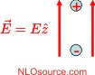
Dipole in an Electric FieldA uniform electric field exerts a force on negative charges that is in a direction opposite to the force on positive charges, resulting in separation of the charges in a material. The equilibrium position is determined by the competition between the force due to the applied field, which acts to separate the charges, with the attractive force between the opposite charges.
As shown above, a uniform electric field results in a dipole moment. The work done in separating the two charges, of magnitude q, by a distance a is given by
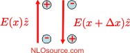
so the energy is a linear function of the applied field and a linear function of the induced dipole moment aq. Quadrupole Moment in a Field GradientWhen the field is non-uniform in space, the electric force on a charge depends on its location. This results in an induced dipole moment that varies from place to place.
In the diagram above, the difference in the electric field at two nearby points is shown to be quantified by a the gradient of the electric field in the x-direction. The resulting dipoles that point in opposite directions is quantified by the quadrupole moment. The work done by the electric field gradient in separating the charges, of magnitude q, by a distance a is given by
The charges reach their equilibrium arrangement when the force exerted by the field gradient matches the internal attractive and repulse force between each pair of charges. Energy of Multipoles in an Electric FieldWe have seen from the description above that an applied electric leads to a rearrangement of the charges. A uniform electric field induces an electric dipole moment and a field gradient induces an electric quadrupole moment. Similarly, the second derivative of an electric field will induce an octupole moment, and so on. The work done by the field is then given by
The charge distribution comes into equilibrium when the work done by the applied field is equal to the work done by the internal fields. Properties of the Induced Dipole MomentA broad range of nonlinear phenomena originates in the induced dipole moment in response to a time varying electric field. As such, we will first focus on the dipole approximation, which assumes that all higher-order moments do not contribute. The physical picture of such phenomena can be framed in the most general terms as follows. An electric field is applied to a material by illuminating it with a single color or multiple colors of light (for example using laser beams) in the presence of static or slowly varying fields, (for example, applied with electrodes connected to a power supply). |
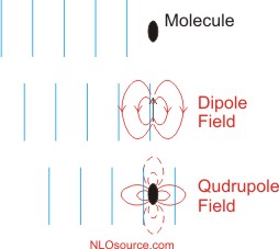
A Plane Wave in MatterIn response to an electric field, the charges in a material separate to form a dipole moment, which adds to the applied electric field. For illustration, consider a plane electromagnetic wave that passes through a molecule. The figure below shows three snapshots at consecutive time intervals. The blue lines are planes of maximum field amplitude.
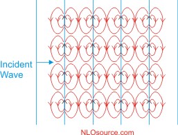
As shown in the diagram above, the induced dipole moment (black arrow) and the resulting dipole field (red pattern) is maximal where the electric field is at its peak. The quadrupole field due to the induced quadrupole moment is the strongest where the field gradient is the largest. In most materials, the time-averaged quadrupole field is much smaller than the time-averaged dipole field. In a linear material, the magnitude of the induced dipole moment is a function of the strength of the electric field at that point. The diagram below shows a plane wave traveling through a material and only shows those dipoles that are induced in the molecules that are at the location of the peak electric field. Since the wave moves to the right, the pattern of induced dipole moments and fields will follow the wave.
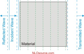
The total electric field in the material is the sum of the electric field of the light beam and the electric field from all of the induced dipole fields. When all of the fields are added together, the result is depicted in the diagram below, there the vertical liens show planes of maximum field amplitude and the material is represented by the gray-shaded area.
The consequence of the addition of the fields leads to the following properties:
|
| <<back to light and matter interactions | continue to polarizability and nonlinear optics>> |